Showing posts with label temperature sensor. Show all posts
Showing posts with label temperature sensor. Show all posts
Tuesday, 16 June 2020

Sunday, 31 May 2020
Home Automation System - Temperature sensor with SONOFF mini - Two sensors
This blog is no longer updated.
To read this post please visit
Monday, 25 May 2020
Home Automation System - Temperature sensor with SONOFF mini - Hardware connection
This blog is no longer updated.
To read this post please visit
Friday, 22 May 2020
Home Automation System - Temperature sensor with SONOFF mini - Software setup
This blog is no longer updated.
To read this post please visit
Friday, 26 October 2018
Home Automation System - Automating a floor lamp


Let's continue with my Home Automation System design, based on the wonderful OpenHAB
This time the main attraction is a simple floor lamp that will be trasformed in a SMART Device, using a Sonoff Basic.
These are my soldiers:

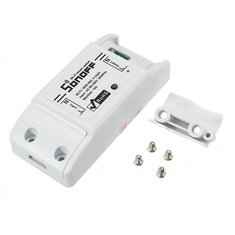
For those who don't know it, SONOFF is a simple "wifi button", which allows you to control electrical loads remotely. The Basic version is the simplest one with a single relay.
It seems a simple job...
I will replace the standard button with the SONOFF...so, I will cut the wires to move away the button from the lamp...and plug these wires in INPUT e OUTPUT pins of the SONOFF.
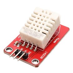
Let the things be a little more complicated: on TASMOTA (https://github.com/arendst/Sonoff-Tasmota/wiki/DHT11-Wiring---Sonoff-Basic), I learnt that it's possible to manage an humidity/temperature sensor, linked to a free pin inside the SONOFF (GPIO14). A compatible sensor is the DHT11 and, luckily, I own some of them.

This sensor has 3 pin, Vin, GND and OUT. So I link Vin and GND to the right SONOFF pins and OUT pin to the GPIO14 (always inside the sonoff)...To discover the right position of these pins, I used again the TASMOTA Wiki (https://github.com/arendst/Sonoff-Tasmota/wiki/GPIO-Locations)
Here are the wires soldered and protected by a heat-shrinking sheath


Now, I have to solder the other side of the wires to the DHT11...

Also here I used a heat-shrinking sheath ...these pins are very close

And here is the complete device...

Now I make an hole in the plastic case to let the wires get out


And here is the lamp with the SONOFF and the DHT11...

Now it's software time. Using the well known TASMOTA web interface, I selected the right sensor connected to the GPIO14.

Back to the home page, I noticed that the data acquired by the DHT11 is displayed on top of the page

Let's configure OpenHAB defining new items and the MQTT topic used by the SONOFF...
My MQTT topic will be smarthome/light_env/%topic%/%prefix%/
Looking to the TASMOTA console, I noticed a new prefix in the topic related to the temperature and humidity information:

This will be the topic which I'll use in the items definition.
Here is the result
Basic UI


And this is the switch for the lamp

-----------------------------------------------------
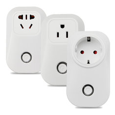
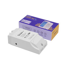
Similar items used in this project
-----------------------------------------------------
Friday, 5 October 2018
Home Automation System - Two PZEM-004T and a single ESP8266
After my successful experiments with the PZEM-004T and a Nodemcu ESP8266 aim to monitor power consumption (devices are actually working well in my ground floor power monitoring system, see https://domoticsduino.blogspot.com/2018/05/home-automation-system-energy.html), I decided to update my photovoltaic production monitoring system, actually based on a Wifi 433Mhz receiver (see https://domoticsduino.blogspot.com/2017/08/home-automation-system-mqtt-and-rf433.html).
Actual system has a problem due to an invalid read of power values when the inverter is switched off. In fact it gives me about 250W power production...
My idea is to use the same devices used for the ground floor power monitoring system...so a PZEM-004T and a Nodemcu ESP8266.
These are the devices:
 |
| NODEMCU ESP8266 |
 |
| PZEM-004T |
Because my inverter is near the electrical panel in the garage, I decided to let the things more complicated adding another PZEM-004T to also monitor the basement consumption with the same ESP8266.
Then I added also a temperature and humidity sensor to the same circuit.
My following step was to check that a single NODEMCU ESP8266 was able to control both PZEM-004T...My tests were successful
Here is it my first PZEM-004T linked to the main output cable of the inverter...on the right you can see the DHT11, temperature and humidity sensor (it's a not so accurate sensor, but it's right for my kind of measurement...)

This is the second PZEM-004T, linked to the main cable of basement power, inside the electrical panel

Complete view:

Now it's time to write the software and test it.
I decided names for the MQTT topics and I created items and sitemap objects for OpenHAB
This is what we could see in my OpenHAB BASIC UI

Energy Consumption value is the sum of all the sensor power (2 of them are already running)
Values are different related to the previous screenshot because they continuously change

Last step: I created some charts in the Grafana dashboard

My primary target was reached: my production monitor give about 0W when the inverter is switched off
Saturday, 25 November 2017
Home Automation System - My first sensors...
After all my experiments, now I'm able to use OpenHAB with familiarity; so now it's time to build my first sensors.
Let's start from the kitchen where I would like to monitor gas, temperature and humidity.
The MCU will be a ESP8266 NodeMcu board. I chose this board because it has wifi, several digital I/O and an analog one, you can write firmware in the same way you could with Arduino and above all...it's very cheap...On Banggood I bought two at only € 2,76 each, not bad...
If you are interested in it, this is the product link:
Geekcreit-Doit-NodeMcu-Lua-ESP8266 on Banggood.com

I will use these sensors:
- MQ-4 gas sensor: for detecting of methane mainly, (I'm interested on it...), propane and butane gas. I already used it months ago. Here is it:

MQ-4 gas sensor on Banggood.com
- Humidity / Temperature sensor DHT11: it'a a very cheap sensor (with about €5 i bought 5); its error is +/- 2°C and it's able to get only positive temperature. Its precision is 1°C, so no decimal number...For these limitations I decided to buy other sensors, the ds18b20 (for internal and external use)...I will use these DHT11 just for humidity

5 pack on Banggood.com
3 Pack on Banggood.com
Single sensor on Banggood.com
- Dallas ds18b20 temperature sensor: compared to the previous one it has a better precision (0,5°C) and it's able to get negative values, so it's ideal for external use

Single sensor on Banggood.com
5 Pack on Banggood.com
External probe on Banggood.com
I built some prototype using a breadboard...

...till I found the right configuration...and so I made a "definitive" board...


I added a led used for the indication of network activity and a connector used for external power. The device will be powered through a little 5V 450mA power adapter, connected to the blue terminal blocks. In this way I could power up the device and also the sensors.
The led, ds18b20 and DHT11 sensors are linked to digital I/O and the MQ-4 gas sensor to the analog one.
Now it's time to write the firmware...I use Visual Studio Code with platformio extension; I think it's better than the Arduino IDE (personal opinion). I chose this IDE because it also has an extension for openHAB that let me edit configuration files in a better way (just like Eclipse SmartHome Designer).
My device will connect to the MQTT broker of OpenHAB through wifi, fetch the data from the sensors and send them as json formatted string with nodemcu/mainfloor/esp8266mcu11/temphumiditygas/state topic.
The sample period is 5 seconds and each 60 seconds the average data will be sent to the MQTT broker. When the data will be sent, the green led will blink twice.
Here is an example of a message sent to the MQTT broker:
{"gas":{"error":"","sensorValue":46.33333,"ppm":0.431016,"percentage":0.000043,"realValue":829.0371},"tempHum":{"error":"","humidity":63.66667,"tempC":22,"tempF":71.59999,"heatIndexC":21.91774,"heatIndexF":71.45234},"temp":{"error":"","tempC":21.66667,"tempF":70.99999}}
The gas object is related to the MQ-4 sensor, the tempHum object is related to the DHT11 sensor and the temp object is related to the ds18b20 sensor.
For now I decided to use both sensors for temperature reading; so I can compare them.
Ok, it seems to work as expected...I put my device in the right place in the kitchen...

Now it's time to setup OpenHAB...and build a new dashboard on Grafana.
In OpenHAB I created a new file called esp8266mcu11.items (esp8266mcu11 is the unique id of the device) in the /etc/openhab2/items folder; in this file I appended the following lines:
Number MainFloor_KitchenTemperature "Kitchen Temperature [%.1f °C]" <temperature>
(gPersistence)
{mqtt="<[openhabianpi-mqtt:nodemcu/mainfloor/esp8266mcu11/temphumiditygas/state:state:JSONPATH($.tempHum.tempC)]" }
Number MainFloor_KitchenTemperatureNew "Kitchen Temperature NEW [%.1f °C]" <temperature>
(gPersistence)
{mqtt="<[openhabianpi-mqtt:nodemcu/mainfloor/esp8266mcu11/temphumiditygas/state:state:JSONPATH($.temp.tempC)]" }
Number MainFloor_KitchenHumidity "Kitchen Humidity [%.1f %%]" <humidity>
(gPersistence)
{mqtt="<[openhabianpi-mqtt:nodemcu/mainfloor/esp8266mcu11/temphumiditygas/state:state:JSONPATH($.tempHum.humidity)]" }
Number MainFloor_KitchenGasPpm "Kitchen Gas [%.2f ppm]" <carbondioxide>
(gPersistence)
{mqtt="<[openhabianpi-mqtt:nodemcu/mainfloor/esp8266mcu11/temphumiditygas/state:state:JSONPATH($.gas.ppm)]" }
Number MainFloor_KitchenGasValue "Kitchen Value [%.2f]" <carbondioxide>
(gPersistence)
{mqtt="<[openhabianpi-mqtt:nodemcu/mainfloor/esp8266mcu11/temphumiditygas/state:state:JSONPATH($.gas.realValue)]" }
Now the sitemap:
Frame label="Gas Detection" {
Text item=MainFloor_KitchenGasPpm valuecolor=[>800="red",>600="orange",<=600="green"]
}
Frame label="Kitchen" {
Text item=MainFloor_KitchenTemperatureNew
Text item=MainFloor_KitchenHumidity
}
And this is the result:

Good, I added a new brick...now I can create the new Grafana dashboard with the gas, humidity and temperature of the kitchen:

Last step: adding the device to the network monitoring...so OpenHAB will notify me when the device will be offline.
So, using PAPERUI I added the device using the Network Binding and create the items. Then I added the gNetworkCheck group to the "status" item, so its network presence will be monitored by OpenHAB.
Sunday, 18 January 2015
First experiment: a simple gas detector
Let's begin assembling some stuff from starter kit...as first example we will try to build a simple "gas detector" using MQ-4 sensor.
Here is the datasheet

The sensor has 3 pins:
- Vcc: 5V supply voltage, Arduino friendly;
- GND: ground connection;
- AD: analog output; provides a value congruent with the gas concentration in the air;
- D0: triggered digital output; provides an HIGH signal when the gas concentration exceeds a limit; you can set this limit through the trigger;

We will use only the analog output, which will be linked to an Arduino's analog input pin.
The sensor needs a pre-heating time.
In our prototype, just for example, we will use also:
- a temp sensor: LM 35
- an LCD display 16X2 backlighted with Hitachi HD44780 driver
- a Buzzer
- a led
- a pot
On the display we will show datas provided by the sensors; led and buzzer will be used to signal warnings and alerts and the pot controls the LCD display dimmer.
Here is the demonstration video:
Subscribe to:
Posts (Atom)