Disclaimer

Please, proceed carefully following the tips published in this blog, specially when Main Power is involved. I'm not responsible for any damages caused by what is written in this blog.
Thank you
Showing posts with label photovoltaic panels. Show all posts

Monday, 24 December 2018

Home Automation System - Let's continue with packages


I'm back...after a lot of time spent at work.

Step by step, I'll reach my goals...no need for hurry...it's a hobby!

Today's target is the packaging of photovoltaic production and basement consumption monitoring system

Here you can find my previous post about it...

http://domoticsduino.blogspot.com/2018/10/home-automation-system-two-pzem-004t.html

As you can see in the following image, it's a mess...and high voltage wires (220v) and PZEM-004T are not safe!


Now finally I'm pretty sure that this monitorin system works well...so it's time to package it, in the best manner I can afford (I'm not so good in manual jobs)😉

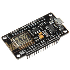
In brief, I have to arrange two PZEM-004T device and a ESP 8266 Mcu, keeping free space for wires and power.

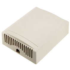
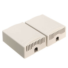
I will use two boxes:


The big one for two PZEM-004T and the small one for the ESP 8266.

To let the wires get out from the box I made some holes in the plastic (I repeat: I'm not so good in manual jobs)


Here is the two PZEM-004T on the bottom of the plastic box. They fit perfectly.


Ok, boxes closed and wires connected again. Here is the final result (a little cleaner than before...)


Next step will be to hang boxes on the wall; now they are just leaning on the wall.
-----------------------------------------------------
Similar items used in this project
-----------------------------------------------------


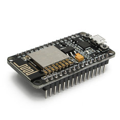
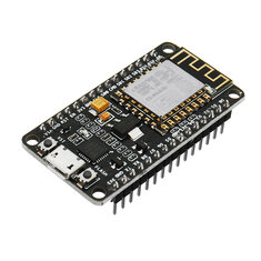
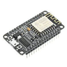
3Pcs Geekcreit® NodeMcu Lua WIFI Internet Things Development Board Based ESP8266 CP2102 Wireless Module

12,66€
Geekcreit® NodeMcu Lua WIFI Internet Things Development Board Based ESP8266 CP2102 Wireless Module

4,11€
3Pcs Geekcreit® NodeMcu Lua ESP8266 ESP-12E WIFI Development Board

13,58€
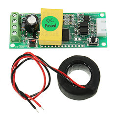
AC Digital Multifunction Meter Ammeter TTL Current Tester Module PZEM-004T With Coil 100A 80-260V

5,25€
10pcs 100 x 80 x 32mm DIY Electronic Plastic Housing Junction Box Power Supply Box Instrument Case Jig Box XL-39

11,60€
2pcs 75 x 54 x 27mm DIY Plastic Project Housing Electronic Junction Case Power Supply Box

1,73€
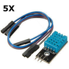
5Pcs KY-015 DHT11 Temperature Humidity Sensor Module For Arduino

7,67€
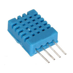
10Pcs DHT11 Digital Temperature Humidity Sensor Module For Arduino

9,31€

Friday, 5 October 2018

Home Automation System - Two PZEM-004T and a single ESP8266


After my successful experiments with the PZEM-004T and a Nodemcu ESP8266 aim to monitor power consumption (devices are actually working well in my ground floor power monitoring system, see https://domoticsduino.blogspot.com/2018/05/home-automation-system-energy.html), I decided to update my photovoltaic production monitoring system, actually based on a Wifi 433Mhz receiver (see https://domoticsduino.blogspot.com/2017/08/home-automation-system-mqtt-and-rf433.html).

Actual system has a problem due to an invalid read of power values when the inverter is switched off. In fact it gives me about 250W power production...

My idea is to use the same devices used for the ground floor power monitoring system...so a PZEM-004T and a Nodemcu ESP8266.

These are the devices:

NODEMCU ESP8266

PZEM-004T

Because my inverter is near the electrical panel in the garage, I decided to let the things more complicated adding another PZEM-004T to also monitor the basement consumption with the same ESP8266.

Then I added also a temperature and humidity sensor to the same circuit.

My following step was to check that a single NODEMCU ESP8266 was able to control both PZEM-004T...My tests were successful

Here is it my first PZEM-004T linked to the main output cable of the inverter...on the right you can see the DHT11, temperature and humidity sensor (it's a not so accurate sensor, but it's right for my kind of measurement...)


This is the second PZEM-004T, linked to the main cable of basement power, inside the electrical panel


Complete view:


Now it's time to write the software and test it.

I decided names for the MQTT topics and I created items and sitemap objects for OpenHAB

This is what we could see in my OpenHAB BASIC UI


Energy Consumption value is the sum of all the sensor power (2 of them are already running)
Values are different related to the previous screenshot because they continuously change


Last step: I created some charts in the Grafana dashboard


My primary target was reached: my production monitor give about 0W when the inverter is switched off

Friday, 24 February 2017

Rf 433 Mhz data "sniffing"


It's been a long time when I wrote my last post...My job and family matters keep me far from my hobbies...priorities won

As some of you could remember (see post http://domoticsduino.blogspot.it/2016/03/data-acquisition-photovoltaic-production.html), I acquired the production of my photovoltaic plant using the OWL CM160 wireless receiver, plugged into the USB port of Raspberry.


Unfortunately, this system was not so stable as I wished, because of the USB driver...and so Raspberry needs to restart...not so convenient...isn't it?

I found an internet blog where someone was able to sniffing wireless data packets trasmitted by the sensor to the OWL, through a simple wireless receiver, as the one I used to receive the gas sensor data...(see post http://domoticsduino.blogspot.it/2015/08/data-acquisition-receiver.html)


This it the article:

https://github.com/onlinux/OWL-CM180

It's using a CM180 wireless receiver, but the explanation works well for the CM160 too.

These systems use the Oregon Scientific communication protocol...My CM160 use the version number 3...

Here is a doc about Oregon Scientific protocol...

DOWNLOAD

Data is transmitted using che Manchester OOK (on off keying) code at 433 Mhz

So I connected my wireless receiver to an Arduino UNO and I downloaded the sketch which allows me to decode the OOK transmission. Playing with bits I was able to decode the transmitted value of the solar power...

Some example in hexadecimal chars:

2a8081bf01501a011900 ==> power 434 W
2a81817f02d0fdf71800 ==> power 627 W
2a81813f0980f3b71300 ==> power 2366 W

Output on the serial port


The next step will be the transmission of received data to central server

Sniffing all the 433 Mhz packets, I noticed that there are packets with a different format...these packets may be transmitted by other sensors. One of these sensor could be the temperature gauge, placed outside the house. At this time I'm not able to decode this particular signal...maybe in the future??

Thursday, 10 March 2016

Data acquisition - Let's take a look...

Finally I'm ready to show acquired data on the web.

I developed a small PHP web application which shows data and charts through the browser.

Some details:

- PHP 5 programming language and HTML5 rendering
- MARIADB database engine (the independent version of MYSQL, bought by Oracle)
- Frontend developed with Bootstrap v.3 framework
- Google Charts library for charts
- jQuery e jQuery-UI Javascript libraries

The User Interface is very simple; it aims to let me verify that all the systems are running fine.

I developed a simple homepage which shows a couple of charts for:

- daily photovoltaic production (link)
- last minutes of Methane Gas detection with a link to a page which shows daily data (link)

Dal grafico della produzione fotovoltaica si può notare un dato anomale...nelle ore notturne la produzione sembra essere costante e maggiore di 0 (cosa naturalmente impossibile...). A detta dell'assistenza, questo problema sembra essere dovuto alla potenza reattiva dovuta alla scarica dei condensatori dell'inverter
From the first chart you can see a strange thing...during the night it seems that photovoltaic production is positive...(impossible, isn't it?). It is due to the reactive power caused by capacitors in the inverter.

(today was a good day...we got 2Kwp)


Under every chart you can also see the last detected data.

On this page there is an auto refresh function which lets you see the real time data.

Then I also developed a login page for future functionalities.


This web application is running on the Raspberry PI, where Apache 2 is installed.
I used a Dynamic DNS service to let this web application be on internet, through a NAT managed by my home router.

I used NO-IP service, which gives me 3 free domains. There is also a linux client application which keeps DNS updated every time my public IP will change.

Tuesday, 8 March 2016

Data acquisition - Photovoltaic production


Another kind of data I would like to acquire is the production of my photovoltaic plant, a 3 kwp plant built over my roof and made by SUNAGE 250 swiss modules and AROS SIRIO inverter.

I also received a little energy monitor tool, which allows me to verify power production through a wireless display. This display is able to store data in a little sqlite database. Through a USB connection, it lets me view and download data using a PC.

This tool is called OWL

http://www.theowl.com/energy-monitors/standalone-monitors/owl-usb/


My model is the OWL+USB CM160.

The OWL has a little bug because it also detects reactive power when the inverter is switched off (during the night for example...)

For my purpose I have to connect OWL to Raspberry. Unfortunately this is not supported and there aren't official drivers. Making some research over the internet, I found a good linux open source interface for OWL: EAGLE-OWL https://github.com/cornetp/eagle-owl

I compiled and installed this software directly into the Raspberry. It is a background process which detects the CM160 e gets the database data.

This is the shell of Raspberry where you can see the eagle-owl software and database files.


This process will run automatically on startup. Then I wrote a little php script which is able to read CM160 database file e put its data into mysql. In this way I could store all historical data which will be displayed through a web interface.

This script will run on Raspberry every minute (standard cron task).