Please, proceed carefully following the tips published in this blog, specially when Main Power is involved. I'm not responsible for any damages caused by what is written in this blog.
Here we are again to speak about energy monitor and OpenHAB. I made some step forward with my experiments.
In the previous post I made some tests with the PZEM-004T Energy Module and an Arduino UNO.
The test was OK...and now I would try to replace Arduino UNO with a cheaper Esp8266 NodeMCU.
There are some differences, because Esp8266 NodeMCU works with 3.3V but Arduino works with 5V, as the PZEM-004T Energy Module.
In the previous test I took 5V from Arduino board and so there was no need to use an external supplier. Now with the Esp8266 NodeMCU it's different because it needs 3.3V.
But...my Esp8266 NodeMCU is a particular model, called LoLin and can be powered with 5V through microUSB cable and it has an output pin with the same voltage as main power.
So, I will use an old power supplier which provides 5V and 400mA.
Let's plug all together.
Last step: the software
Let's use the same software used for Arduino, just to check the everything works well.
Here is the serial output.
18W lamp:
100W lamp:
It's all OK...nice!
Let's edit the software to introduce MQTT protocol. This is the idea: if energy values are similar, I will send the data every 1 minute; otherwise, when a value differs from the previous one, send the data immediately.
This is my MQTT topic (just for testing purpose)
nodemcu/test/esp8266mcu12/powerconsumption/state
using MQTT-SPY I check the transmission:
All work as expected...
My next job will be to integrate this device with OpenHAB and see the data on its sitemap and on Grafana dashboard
After a little stop, I'm going to tell you about my Home Automation System.
In particular, I would like to speak about some test I made to build a power monitoring system. I'm trying to build something easily integrable in OpenHAB. I need a system able to acquire data and send them to OpenHAB, to be remotely accessible and use them to trigger alarms and notifications.
I need a little device which can be plugged in some junction box...
Looking for it on internet I found the Eastron sdm120c Modbus...
A nice product which can be query through its RS485 serial interface to fetch data about energy consumption (voltage, current, power, etc etc). It can be easily connected to an Arduino or Raspberry. I was buying it when I found this one:PZEM-004T Energy Module, a little device with a current clamp able to get power consumption. It has a serial interface and so its data can be read by Arduino / Raspberry. It has little dimensions and it's very cheap. I bought it for 8€, shipped at home
Currently I bought only one...if my tests will be ok, I'll buy others. Mi target is to monitor home power consumption for each floor. Now I have to choose a MCU. I would like to use a Esp8266 NodeMCU; it's a little device, has built in wifi capabilities and is very cheap! If it will not work as expected, I will use an Arduino board. Ok, let's begin with some experiment just to see if PZEM-004T Energy Module will work. I will use an Arduino board because it's easier to plug than the ESP8266 NodeMcu
If it will work good, I'll try the ESP8266 NodeMcu. The device needs 5V for the low-voltage side and 220v for the power line
Let's begin to plug:
GND and 5V from Arduino to the device;
serial output from the device to 2 Arduino GPIO
To test a load, I will use a simple lamp.
I downloaded a simple software for Arduino, which writes the data acquired on the serial output. Here is the output when the lamp is switched off: no current, no power:
Switch on the lamp...
and we get the power...
Perfect. It works as expected. Next step will be to use an Esp8266 NodeMCU instead of Arduino and then use MQTT tu send data to OpenHAB.
I can't believe it!!! I reached a little goal...Home Alarm and OpenHAB together...
I know...It seems a simple thing...today home alarm systems can be remote controlled ... but the old ones (as mine is...) don't...
My target was to view the input status of all sensors / radars in my home alarm system...I don't like remote controller...just remote monitoring...
So, it's quite simple: I have to integrate all sensors / radars with a device, as Arduino or similar ones, and gets the input status (OPEN / CLOSE).
I have to know what kind of signal is transmitted by sensors / radars...I discovered the wires from the sensors / radar and with the tester I found the voltage is about 4.5v when the signal is HIGH and 0 when the signal is low.
I made some test with my main entrance door so I confirmed this behaviuor. Door OPEN, 4.5v on the terminal...DOOR closed, 0 voltage.
Now, I have to find a device with at least 11 GPIO 4.5v tolerant
I can choose between:
- a NodeMCU ESP8266 device, with integrated wifi; but it accepts only 4 volts
- an Arduino UNO with ethernet shield, with GPIO 5v tolerant;
The first choice would be the best, because we have integrated wifi and a very small layout...but I have to step down voltage from 4.5v to 3.3v (max)
Otherwise, using Arduino UNO, the voltage is already OK but I need a new shield (ethernet shield)
Idea!!!!!
Raspberry PI3 where OpenHAB and MQTT broker are running, has a lot of GPIO on its board. I could use them. But these GPIO works with 3.3v max. No problem...I will build an interface device with voltage divider...
- take all alarm input wires to the Raspberry PI3
- build an interface to step down voltage from 4.5v to 3.3v
- download and setup of GPIO binding of OpenHAB (see https://github.com/openhab/openhab1-addons/wiki/GPIO-Binding)
- make a new sitemap to see the alarm device input
In the next post, I will descrive the operational phase of work
Now I will try to integrate my RF433 Wireless Receiver (built on Arduino with Ethernet Shield) with MQTT, just to acquire my photovoltaic production data in my future Home Automation System
I don't write nothing more about my acquisition system; this is my old post about that:
Now I would like to transmit data to my MQTT broker, for the future integration with OpenHAB
So, I have to edit the code of the Arduino sketch and let it to publish messages to the MQTT broker. In this time, the receiver publishes data to a HTTP REST Web Service
Well, using Arduino IDE (the same thing used for the SONOFF firmware upload), I open the sketch and edit the code.
I omit the technical details about the code because it's not the purpose of this post, but if you are interested in it, write me an email; I will be happy to share my code with you.
I chose the following MQTT topic:
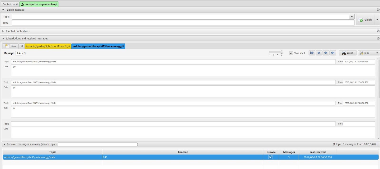
arduino/groundfloor/rf433/solarenergy/state
I followed the same naming convention as the SONOFF :
[device]/[zone]/[type]/[data id]/state
The content of the message is simply the value of the production in Watt.
Here are the published messages, through mqtt-spy:
And here is the receiver:
Currently it's "mute", but the next step would be adding a led to monitor its status and eventually some environmental sensor...
Unfortunately, this system was not so stable as I wished, because of the USB driver...and so Raspberry needs to restart...not so convenient...isn't it?
I found an internet blog where someone was able to sniffing wireless data packets trasmitted by the sensor to the OWL, through a simple wireless receiver, as the one I used to receive the gas sensor data...(see post http://domoticsduino.blogspot.it/2015/08/data-acquisition-receiver.html)
Data is transmitted using che Manchester OOK (on off keying) code at 433 Mhz
So I connected my wireless receiver to an Arduino UNO and I downloaded the sketch which allows me to decode the OOK transmission. Playing with bits I was able to decode the transmitted value of the solar power...
Some example in hexadecimal chars:
2a8081bf01501a011900 ==> power 434 W 2a81817f02d0fdf71800 ==> power 627 W 2a81813f0980f3b71300 ==> power 2366 W
Output on the serial port
The next step will be the transmission of received data to central server
Sniffing all the 433 Mhz packets, I noticed that there are packets with a different format...these packets may be transmitted by other sensors. One of these sensor could be the temperature gauge, placed outside the house. At this time I'm not able to decode this particular signal...maybe in the future??
I'm going to use it as a remote gas sensor with MQ-4 [Datasheet].
and a wireless RF-433 transmitter.
with a lot of wire, led and a push button to reset sensor status.
HARDWARE
This is the fritzling design:
As well as Wireless transmitter and gas sensor, we could see a red led, a green led and a RGB led. On the left side of the schema, there is also a push button. Led are powered by Arduino 5V power line, protected by resistors...Arduino is powered by a 12V transformer just like the wireless transmitter, to ensure the best transmission power.
PIN 11: push-button
PIN A1: analogue pin linked to GAS sensor
PIN 9: wireless data transmission
PIN 12: red led for wireless activity indication PIN 8: green led for data acquisition activity PIN 3, 5 and 6: RGB led for showing system status - off: normal values;
- yellow: an out of tolerance value under the danger threshold;
- rosso: an out of tolerance value over the danger threshold;
Here is it:
FUNCTIONALITY AND MESSAGES
When the system is powered up, the gas sensor warm up stage starts; this is necessary to ensure better precision...during this time, RGB led blinks.
Then, data acquisition starts.
Every second the system gets 10 samples data from the sensor (the green led flashes every second) and calculates the average...Every 5 seconds the average of the collected values is sent to the receiver (the red led flashes every 5 seconds).
When the average is out of tolerance, RGB led lights up.
The push buttons reset the system status and turns off the RGB led. If a value is out of tolerance and then other samples return to normal values, the led still lights on...to get the attention...only through the push button, led could be turned off.
The wireless data sent every 5 seconds is a text string with the following format:
GAS;VALUE;STATUS|
VALUE is the calculated average, STATUS is a numeric value indicating the system status according to the following schema:
- 1: ok;
- 2: warning
- 3: danger
SOFTWARE
You can download the complete Arduino Sketch from here:
It's time for the second experiment.
The Ethernet Shield test with Arduino Uno Rev 3.
We will put the shield on the local network and create a simple web server which will reply to http request and will drive two led.
There is a useful library which will help to develop the Ethernet Shield software. With some line of code the device will be on the LAN using DHCP protocol or by setting manual configuration (ip, dns, gateway ...)
The shield will be directly linked to Arduino. Pin 10, 11, 12, 13 are used by the shield and so they cannot be used by developers.
For our purpose, we will link digital output 2 and 8 to two led. Arduino will drive them, receiving http requests. A tablet will be used as client.
Our Arduino will listen on port 80 and will drive the led, managing http requests.
- Vcc: 5V supply voltage, Arduino friendly;
- GND: ground connection;
- AD: analog output; provides a value congruent with the gas concentration in the air;
- D0: triggered digital output; provides an HIGH signal when the gas concentration exceeds a limit; you can set this limit through the trigger;
We will use only the analog output, which will be linked to an Arduino's analog input pin.
The sensor needs a pre-heating time.
In our prototype, just for example, we will use also:
- a temp sensor: LM 35
- an LCD display 16X2 backlighted with Hitachi HD44780 driver
- a Buzzer
- a led
- a pot
On the display we will show datas provided by the sensors; led and buzzer will be used to signal warnings and alerts and the pot controls the LCD display dimmer.