Disclaimer

Please, proceed carefully following the tips published in this blog, specially when Main Power is involved. I'm not responsible for any damages caused by what is written in this blog.
Thank you
Showing posts with label arduino. Show all posts

Saturday, 10 March 2018

Home Automation System - Energy consumption monitor...the first test


After a little stop, I'm going to tell you about my Home Automation System.

In particular, I would like to speak about some test I made to build a power monitoring system.

I'm trying to build something easily integrable in OpenHAB. I need a system able to acquire data and send them to OpenHAB, to be remotely accessible and use them to trigger alarms and notifications.

I need a little device which can be plugged in some junction box...

Looking for it on internet I found the Eastron sdm120c Modbus...


A nice product which can be query through its RS485 serial interface to fetch data about energy consumption (voltage, current, power, etc etc). It can be easily connected to an Arduino or Raspberry.

I was buying it when I found this one: PZEM-004T Energy Module, a little device with a current clamp able to get power consumption. It has a serial interface and so its data can be read by Arduino / Raspberry. It has little dimensions and it's very cheap. I bought it for 8€, shipped at home


Currently I bought only one...if my tests will be ok, I'll buy others. Mi target is to monitor home power consumption for each floor.

Now I have to choose a MCU. I would like to use a Esp8266 NodeMCU; it's a little device, has built in wifi capabilities and is very cheap! If it will not work as expected, I will use an Arduino board.

Ok, let's begin with some experiment just to see if PZEM-004T Energy Module will work. I will use an Arduino board because it's easier to plug than the ESP8266 NodeMcu

If it will work good, I'll try the ESP8266 NodeMcu.

The device needs 5V for the low-voltage side and 220v for the power line

Let's begin to plug:
  • GND and 5V from Arduino to the device;
  • serial output from the device to 2 Arduino GPIO


To test a load, I will use a simple lamp.


I downloaded a simple software for Arduino, which writes the data acquired on the serial output. Here is the output when the lamp is switched off: no current, no power:


Switch on the lamp...


and we get the power...


Perfect. It works as expected. Next step will be to use an Esp8266 NodeMCU instead of Arduino and then use MQTT tu send data to OpenHAB.

Friday, 19 January 2018

Home Automation System - Alarm and OpenHAB...my idea


I can't believe it!!! I reached a little goal...Home Alarm and OpenHAB together...

I know...It seems a simple thing...today home alarm systems can be remote controlled ... but the old ones (as mine is...) don't...

My target was to view the input status of all sensors / radars in my home alarm system...I don't like remote controller...just remote monitoring...

So, it's quite simple: I have to integrate all sensors / radars with a device, as Arduino or similar ones, and gets the input status (OPEN / CLOSE).

I have to know what kind of signal is transmitted by sensors / radars...I discovered the wires from the sensors / radar and with the tester I found the voltage is about 4.5v when the signal is HIGH and 0 when the signal is low.

I made some test with my main entrance door so I confirmed this behaviuor. Door OPEN, 4.5v on the terminal...DOOR closed, 0 voltage.

Now, I have to find a device with at least 11 GPIO 4.5v tolerant

I can choose between:

- a NodeMCU ESP8266 device, with integrated wifi; but it accepts only 4 volts


- an Arduino UNO with ethernet shield, with GPIO 5v tolerant;


The first choice would be the best, because we have integrated wifi and a very small layout...but I have to step down voltage from 4.5v to 3.3v (max)

Otherwise, using Arduino UNO, the voltage is already OK but I need a new shield (ethernet shield)

Idea!!!!!


Raspberry PI3 where OpenHAB and MQTT broker are running, has a lot of GPIO on its board. I could use them. But these GPIO works with 3.3v max. No problem...I will build an interface device with voltage divider...

Then I could use an OpenHAB bindings (see https://github.com/openhab/openhab1-addons/wiki/GPIO-Binding) to manage GPIO, so no needs for an external software...

Summarizing:

 - take all alarm input wires to the Raspberry PI3
 - build an interface to step down voltage from 4.5v to 3.3v
 - download and setup of GPIO binding of OpenHAB (see https://github.com/openhab/openhab1-addons/wiki/GPIO-Binding)
 - make a new sitemap to see the alarm device input

In the next post, I will descrive the operational phase of work

Monday, 28 August 2017

Home Automation System - MQTT and RF433 to monitor photovoltaic production


Now I will try to integrate my RF433 Wireless Receiver (built on Arduino with Ethernet Shield) with MQTT, just to acquire my photovoltaic production data in my future Home Automation System

I don't write nothing more about my acquisition system; this is my old post about that:

http://domoticsduino.blogspot.com/2017/02/rf-433-mhz-data-sniffing.html

Now I would like to transmit data to my MQTT broker, for the future integration with OpenHAB

So, I have to edit the code of the Arduino sketch and let it to publish messages to the MQTT broker. In this time, the receiver publishes data to a HTTP REST Web Service

Well, using Arduino IDE (the same thing used for the SONOFF firmware upload), I open the sketch and edit the code.

I omit the technical details about the code because it's not the purpose of this post, but if you are interested in it, write me an email; I will be happy to share my code with you.

I chose the following MQTT topic:

arduino/groundfloor/rf433/solarenergy/state

I followed the same naming convention as the SONOFF :

[device]/[zone]/[type]/[data id]/state

The content of the message is simply the value of the production in Watt.

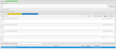
Here are the published messages, through mqtt-spy:


And here is the receiver:


Currently it's "mute", but the next step would be adding a led to monitor its status and eventually some environmental sensor...

Stay tuned...


Saturday, 29 August 2015

Data Acquisition - Remote Gas Detector


Now, it's time to connect a remote sensor to my new receiver and begin a real data acquisition.

I think I'll go back to my sensor gas prototype...I already made some experiments with it:

First experiment: a simple gas detector

I'm going to use it as a remote gas sensor with MQ-4 [Datasheet].


and a wireless RF-433 transmitter.


with a lot of wire, led and a push button to reset sensor status.

HARDWARE

This is the fritzling design:


As well as Wireless transmitter and gas sensor, we could see a red led, a green led and a RGB led. On the left side of the schema, there is also a push button. Led are powered by Arduino 5V power line, protected by resistors...Arduino is powered by a 12V transformer just like the wireless transmitter, to ensure the best transmission power.

PIN 11: push-button

PIN A1: analogue pin linked to GAS sensor

PIN 9: wireless data transmission

PIN 12: red led for wireless activity indication
PIN 8: green led for data acquisition activity
PIN 3, 5 and 6: RGB led for showing system status
 - off: normal values;
 - yellow: an out of tolerance value under the danger threshold;
 - rosso: an out of tolerance value over the danger threshold;

Here is it:


FUNCTIONALITY AND MESSAGES

When the system is powered up, the gas sensor warm up stage starts; this is necessary to ensure better precision...during this time, RGB led blinks.

Then, data acquisition starts.

Every second the system gets 10 samples data from the sensor (the green led flashes every second) and calculates the average...Every 5 seconds the average of the collected values is sent to the receiver (the red led flashes every 5 seconds).

When the average is out of tolerance, RGB led lights up.

The push buttons reset the system status and turns off the RGB led. If a value is out of tolerance and then other samples return to normal values, the led still lights on...to get the attention...only through the push button, led could be turned off.

The wireless data sent every 5 seconds is a text string with the following format:

GAS;VALUE;STATUS|

VALUE is the calculated average, STATUS is a numeric value indicating the system status according to the following schema:

 - 1: ok;
 - 2: warning
 - 3: danger

SOFTWARE

You can download the complete Arduino Sketch from here:

DOWNLOAD

As for the receiver, I used RADIOHEAD libraries to manage wireless transmitter.

Setup:

- wireless receiver setup;

- status led setup;

- MQ-4 sensor warm up;

Main loop:

- First, the system checks the push button status...If it was pressed, the variable which manages the system status will be set to OFF;

- Then, the system read 10 samples from the gas sensor and calculates their average; during this time the green led lights up (PIN 8);

- Every 5 seconds the system calculates the average and set the system status according to this value; then, this value is sent to the receiver;

- In case of out of tolerance value, RGB status led (PIN 3, 5 e 6) will light up;

- The average value is sent to the receiver; during this time the green led (PIN 12) will light up;

And finally, here is a short video:


Saturday, 8 August 2015

Data acquisition - The Receiver


Let's get started with the first component: The Receiver.

Here is it still as a prototype


It's made up by an Arduino Uno Board, with the ethernet shield to get network access and the wireless RF433 receiver

Functionality and communication protocols

The wireless receiver receives messages sent by sensors and then route them towards WEB/APP server, using http protocol. It acts as a simple router.

Communication protocols are very simple and currently not secure, so for now this system cannot be in a public network.

The message sent by sensors is a character string made up in the following way:

SENSOR;VALUE;STATUS|

where SENSOR is the name of the sensor; VALUE is the current value of the sensor and STATUS is a particular condition for the sensor (DANGER, WARNING, and so on...)

The receiver gets this string and send it to the WEB/APP server, using the following HTTP GET request:

http://SERVERNAME/data.php?u=PASSWORD&d=STRING

where SERVERNAME is the domain in which WEB App is installed, PASSWORD is a secret key known also by the WEB/APP server and STRING is the sensor's data.

As already said, communication protocol is very simple and without ACK...for now it's just a prototype and it aims only to debug system

HARDWARE

Fritzling Schema (approx)


PIN 2 OUTPUT for RF status led (RED), reporting wireless activity;
PIN 3 OUTPUT for ETH status led (GREEN), reporting ethernet activity;
PIN 5V to power up wireless received and led;
PIN GND linked to wireless receiver GND pin;
PIN 7 INPUT to receive wireless data;

The Ethernet shield is linked to Arduino UNO; all the system is powered up by external 5V.

SOFTWARE

Setup

- wireless receiver setup using RadioHead library;

- ethernet shield setup using standard Ethernet library; it this case we use a static IP (but you can use DHCP if your network provides it);

- status led setup;

Main Loop

- the main thread wait for a wireless message;

- after received a new message, RF status led lights up and the message is sent to WEB/APP server using HTTP request;

- during the http request, ETH status led lights up and it turns off after the HTTP response;

Here you can find source code for the receiver: DOWNLOAD

And here is a video about the receiver doing its job...


Saturday, 1 August 2015

My first project - data acquisition system


I started design my first data-acquisition system with Raspberry PI and Arduino. The idea is to have a sensors network which send data to a receiver which, through ethernet, send these data to WEB/APP server.

The main components are:

- one or more sensors
- a receiver
- a DB Server for storage purpouse
- a WEB/APP server to acquire data and let remote user monitoring the system

Here is the design:


More details:

SENSORS

They can send data in different ways:

- wireless RF-433 towards receiver
- ethernet towards receiver
- USB directly towards server

They can be Arduino board or Raspberry PI or others...
Depending on the type of communication, there can be other interface boards or control led...

RECEIVER

It receives data via wireless RF-433 or via Ethernet
Through ethernet, it transmits data to WEB/APP server, for storage and monitoring purpose

It's built over an Arduino boards with Ethernet Shield and wireless RF-433 receiver. There are also control led.

WEB/APP SERVER

It receives data from receiver through ethernet or from sensor directly connected on its USB port
It stores data on DB server
It runs a web application for remote monitoring

The WEP/APP server software is the world famous Apache HTTPD, installed on Raspberry, running Fedora linux distro.

The monitoring web application is written in PHP / HTML5 using Bootstrap framework, which make it responsive.

DB SERVER

It stores data received from WEB/APP server.

The RDBMS is Mysql Community Edition installed on the same Raspberry of WEB/APP server

Friday, 31 July 2015

Arduino Low Cost Wireless Link


It's been a while since my last post...but my job kept me busy and I was not able to continue with my experiments with Arduino e Raspberry.

But in the last few weeks I was able to get back to Arduino

If you remember, some month ago I bought two wireless RF-433 modules (transmitter and receiver)


So, I made some experiment, linking two Arduino boards, using RadioHead libraries.

Then I built a little home-made antenna over both modules...and I used a 12V adapter on the trasmitter, in order to get the best range.

This is the receiver:


...and this is the trasmitter:


My test was very simple...I tried to send some text string from one Arduino to the other...the receiver was connected to the PC just to verify through serial port console the received messages.

Test was OK...it's time to build something useful...

Sunday, 11 January 2015

A new adventure...


Welcome everybody in this new adventure related to eletric / electronic and computer world...

Finally, after a lot of time spent on thoughts and searches over the internet, I decided to enter in the world of Arduino boards...

Electronic and computer things always involved me a lot...and thanks to Piero's suggestions, I filled my electronic gaps and so now I'm able to design and build something useful.

Who already follows me, knows that I'm involved, always with the help of Piero, in another ambitious and exciting project: the building of a flight simulator cockpit (details on www.mylearjet45.net)

Instead, in this blog, I would like to write about my attempts to design and build something related to domotics (home automation)...mainly using Arduino and Raspberry PI boards, with related extensions...

What are Arduino and Raspberry PI?

Arduino


Arduino is an open-source electronics platform based on easy-to-use hardware and software. It's intended for anyone making interactive projects. There is a wide range of products, based on technical characteristics and dimensions...

The Starter Kits (Arduino board plus a good range of useful accessories) are very useful for the beginners.

Through input/output pins and software programming, you can interface sensors and actuators in the real world...

There are a lot of expansion cards (called shield) as Wifi/Ethernet connectivity, Infrared/Bluetooth transceiver, Sd Card Reader and so on...

The programming language is based on C language and you can find a lot of examples over the internet.

References and official website www.arduino.cc

Raspberry PI


Unlike Arduino, Raspberry PI is a real, small (credit card size) and low power consumption PC, and is able to run many Linux Distros. It has many USB ports, HDMI Output, 3.5mm A/V Jack, CPU and Ram...

Link Arduino it has many GPIO (General Purpouse Input Output) pins to interface real world sensors and actuators.

There is a wide range of models...the last one (February 2015) is Raspberry Pi 2 Model B. These are its technical characteristics:

  • A 900MHz quad-core ARM Cortex-A7 CPU
  • 1GB RAM
  • 4 USB ports
  • 40 GPIO pins
  • Full HDMI port
  • Ethernet port
  • Combined 3.5mm audio jack and composite video
  • Camera interface (CSI)
  • Display interface (DSI)
  • Micro SD card slot
  • VideoCore IV 3D graphics core

References and official website www.raspberrypi.org

Both boards, used together, could be used to design infinite projects...fantasy is the only limit...

Now it's time to begin...with Arduino...

...we are waiting for the Starter Kit Arduno Uno Rev 3...

Stay tuned