Please, proceed carefully following the tips published in this blog, specially when Main Power is involved. I'm not responsible for any damages caused by what is written in this blog.
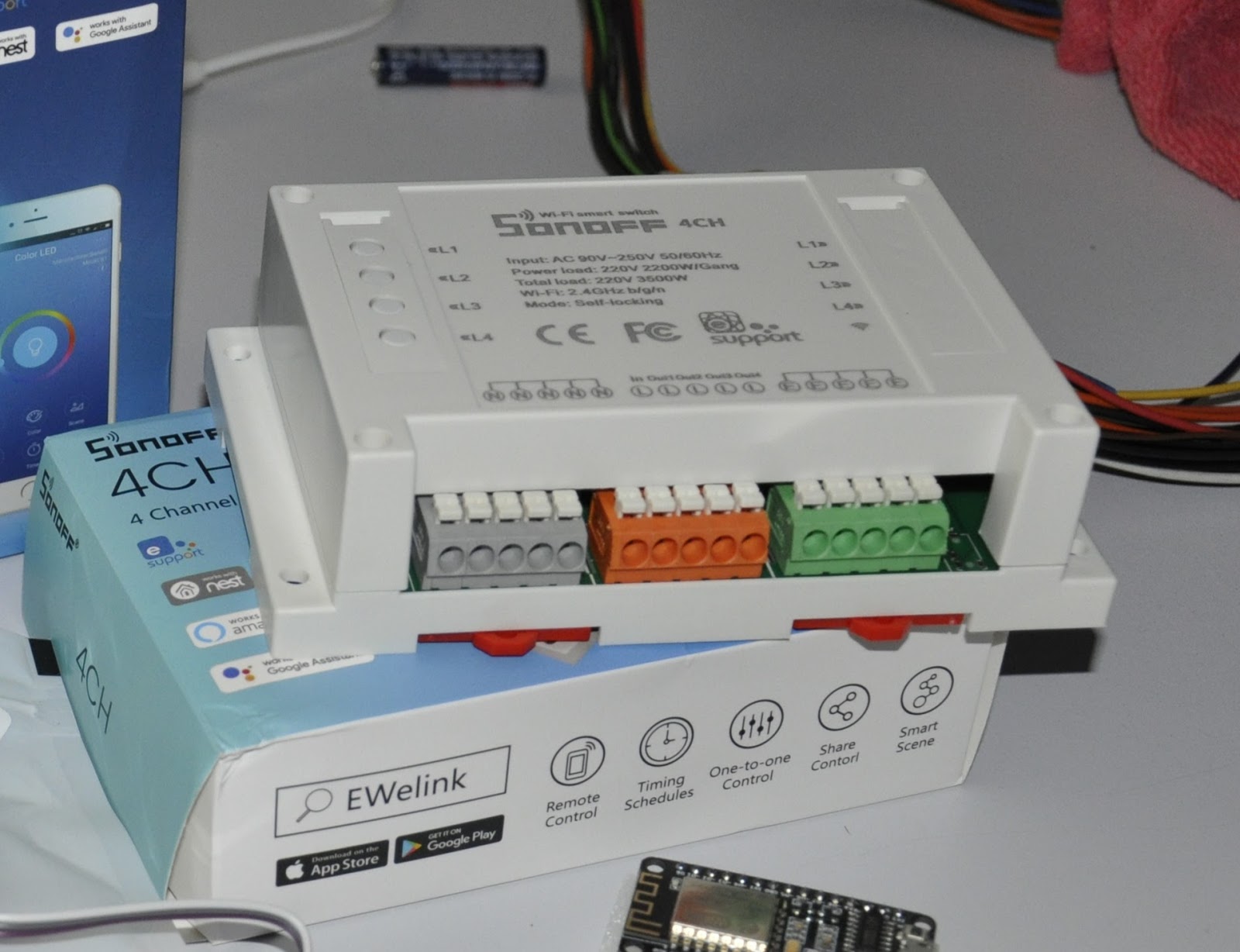
In the previous post, I spoke about my SONOFF 4 channel, describing the physical installation.
Now, this device will help me to drive 4 lights: 1 internal and 3 exterior; of course, OpenHAB will be my control system and MQTT will be the message protocol.
Let's go to setup the SONOFF, using its web interface
The first step will be to setup the module type, using the menù Configuration -> Configure Module
Then, in Configuration -> Configure MQTT, we will put the MQTT topic, splitted in TOPIC and FULLTOPIC as TASMOTA ask
In my case the device will use the following topic smarthome/sonoff4ch14/###. TASMOTA will replace ### with the type of message it will be sending (for example cmnd for commands, state for status information etc etc) No more details on the other configuration options...they are the same as the other SONOFF
Now it's time for OpenHAB...we will add 4 items, one for each light.
Create a new file, called sonoff4ch.items, in the usual folder /etc/openhab2/items; in the file we will write the items configuration:
As you can see, MQTT topic is the same for all items. Only one thing changes...the property name, indexed by a number to indicate the relay number.
Finally, the last step: put the 4 items into a sitemap. So, write down 4 switch into the sitemap file
Finally I found a little time to continue my Home Automation System.
I already own a SONOFF 4 channel...I think the biggest one...
This device is able to drive 4 power outputs through a single Wifi connection. I will use it to power up my lights.
As well as input and output power connector,s it also has 4 pushbuttons which drive the 4 relays. Basically it's like 4 SONOFF Basic in a single device and with a single Wifi connection.
As usual I will use the TASMOTA firmware instead of the original one, which permits to use the device only through EWelink software. With TASMOTA firmware I'm able to easily integrate the device in OpenHAB using MQTT protocol.
Here is my SONOFF in flashing mode
As usual, it's easy to flash the firmware...just follow the official Wiki
Please, remember that this is an irreversible operation. You cannot recover the original firmware
In order to be able to control the SONOFF also through a traditional button, I decided to use the 4 pushbuttons integrated in the device... by connecting them appropriately to the buttons / wall switches ...
I never throw anything away and in this case a male / female old serial cable will be very useful to connect comfortably and plug and play the buttons / wall switches with the SONOFF buttons.
Thanks to Piero, we soldered the serial pins to the 4 pushbuttons on the SONOFF
getting the connector out of the SONOFF box
On the other side, we have an ethernet cable linked to the wall buttons
and we soldered to it the male serial connector
Ok, now it's time to configure the device to be integrated in OpenHAB through MQTT
Last Friday, a new mailbag arrived...full of new stuffs from China...
Among the others, we have:
- a SONOFF B1, wifi controlled RGB lamp;
- a SONOFF 4Ch, wifi controlled relays (4);
- some temperature and humidity sensors DHT11
- some RF433 wireless transmitter and receiver
- a couple of ESP8266 NodeMCU
Unfortunately, this system was not so stable as I wished, because of the USB driver...and so Raspberry needs to restart...not so convenient...isn't it?
I found an internet blog where someone was able to sniffing wireless data packets trasmitted by the sensor to the OWL, through a simple wireless receiver, as the one I used to receive the gas sensor data...(see post http://domoticsduino.blogspot.it/2015/08/data-acquisition-receiver.html)
Data is transmitted using che Manchester OOK (on off keying) code at 433 Mhz
So I connected my wireless receiver to an Arduino UNO and I downloaded the sketch which allows me to decode the OOK transmission. Playing with bits I was able to decode the transmitted value of the solar power...
Some example in hexadecimal chars:
2a8081bf01501a011900 ==> power 434 W 2a81817f02d0fdf71800 ==> power 627 W 2a81813f0980f3b71300 ==> power 2366 W
Output on the serial port
The next step will be the transmission of received data to central server
Sniffing all the 433 Mhz packets, I noticed that there are packets with a different format...these packets may be transmitted by other sensors. One of these sensor could be the temperature gauge, placed outside the house. At this time I'm not able to decode this particular signal...maybe in the future??
I'm going to use it as a remote gas sensor with MQ-4 [Datasheet].
and a wireless RF-433 transmitter.
with a lot of wire, led and a push button to reset sensor status.
HARDWARE
This is the fritzling design:
As well as Wireless transmitter and gas sensor, we could see a red led, a green led and a RGB led. On the left side of the schema, there is also a push button. Led are powered by Arduino 5V power line, protected by resistors...Arduino is powered by a 12V transformer just like the wireless transmitter, to ensure the best transmission power.
PIN 11: push-button
PIN A1: analogue pin linked to GAS sensor
PIN 9: wireless data transmission
PIN 12: red led for wireless activity indication PIN 8: green led for data acquisition activity PIN 3, 5 and 6: RGB led for showing system status - off: normal values;
- yellow: an out of tolerance value under the danger threshold;
- rosso: an out of tolerance value over the danger threshold;
Here is it:
FUNCTIONALITY AND MESSAGES
When the system is powered up, the gas sensor warm up stage starts; this is necessary to ensure better precision...during this time, RGB led blinks.
Then, data acquisition starts.
Every second the system gets 10 samples data from the sensor (the green led flashes every second) and calculates the average...Every 5 seconds the average of the collected values is sent to the receiver (the red led flashes every 5 seconds).
When the average is out of tolerance, RGB led lights up.
The push buttons reset the system status and turns off the RGB led. If a value is out of tolerance and then other samples return to normal values, the led still lights on...to get the attention...only through the push button, led could be turned off.
The wireless data sent every 5 seconds is a text string with the following format:
GAS;VALUE;STATUS|
VALUE is the calculated average, STATUS is a numeric value indicating the system status according to the following schema:
- 1: ok;
- 2: warning
- 3: danger
SOFTWARE
You can download the complete Arduino Sketch from here:
Let's get started with the first component: The Receiver.
Here is it still as a prototype
It's made up by an Arduino Uno Board, with the ethernet shield to get network access and the wireless RF433 receiver
Functionality and communication protocols
The wireless receiver receives messages sent by sensors and then route them towards WEB/APP server, using http protocol. It acts as a simple router.
Communication protocols are very simple and currently not secure, so for now this system cannot be in a public network.
The message sent by sensors is a character string made up in the following way:
SENSOR;VALUE;STATUS|
where SENSOR is the name of the sensor; VALUE is the current value of the sensor and STATUS is a particular condition for the sensor (DANGER, WARNING, and so on...)
The receiver gets this string and send it to the WEB/APP server, using the following HTTP GET request:
http://SERVERNAME/data.php?u=PASSWORD&d=STRING
where SERVERNAME is the domain in which WEB App is installed, PASSWORD is a secret key known also by the WEB/APP server and STRING is the sensor's data.
As already said, communication protocol is very simple and without ACK...for now it's just a prototype and it aims only to debug system
HARDWARE
Fritzling Schema (approx)
PIN 2 OUTPUT for RF status led (RED), reporting wireless activity; PIN 3 OUTPUT for ETH status led (GREEN), reporting ethernet activity; PIN 5V to power up wireless received and led; PIN GND linked to wireless receiver GND pin; PIN 7 INPUT to receive wireless data;
The Ethernet shield is linked to Arduino UNO; all the system is powered up by external 5V.
SOFTWARE
Setup
- wireless receiver setup using RadioHead library;
- ethernet shield setup using standard Ethernet library; it this case we use a static IP (but you can use DHCP if your network provides it);
- status led setup;
Main Loop
- the main thread wait for a wireless message;
- after received a new message, RF status led lights up and the message is sent to WEB/APP server using HTTP request;
- during the http request, ETH status led lights up and it turns off after the HTTP response;
Here you can find source code for the receiver: DOWNLOAD
And here is a video about the receiver doing its job...
I started design my first data-acquisition system with Raspberry PI and Arduino. The idea is to have a sensors network which send data to a receiver which, through ethernet, send these data to WEB/APP server.
The main components are:
- one or more sensors
- a receiver
- a DB Server for storage purpouse
- a WEB/APP server to acquire data and let remote user monitoring the system
Here is the design:
More details:
SENSORS
They can send data in different ways:
- wireless RF-433 towards receiver
- ethernet towards receiver
- USB directly towards server
They can be Arduino board or Raspberry PI or others...
Depending on the type of communication, there can be other interface boards or control led...
RECEIVER
It receives data via wireless RF-433 or via Ethernet
Through ethernet, it transmits data to WEB/APP server, for storage and monitoring purpose
It's built over an Arduino boards with Ethernet Shield and wireless RF-433 receiver. There are also control led.
WEB/APP SERVER
It receives data from receiver through ethernet or from sensor directly connected on its USB port
It stores data on DB server
It runs a web application for remote monitoring
The WEP/APP server software is the world famous Apache HTTPD, installed on Raspberry, running Fedora linux distro.
The monitoring web application is written in PHP / HTML5 using Bootstrap framework, which make it responsive.
It's been a while since my last post...but my job kept me busy and I was not able to continue with my experiments with Arduino e Raspberry.
But in the last few weeks I was able to get back to Arduino
If you remember, some month ago I bought two wireless RF-433 modules (transmitter and receiver)
So, I made some experiment, linking two Arduino boards, using RadioHead libraries.
Then I built a little home-made antenna over both modules...and I used a 12V adapter on the trasmitter, in order to get the best range.
This is the receiver:
...and this is the trasmitter:
My test was very simple...I tried to send some text string from one Arduino to the other...the receiver was connected to the PC just to verify through serial port console the received messages.
Test was OK...it's time to build something useful...